


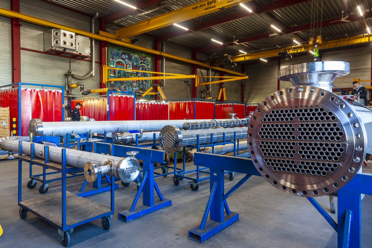
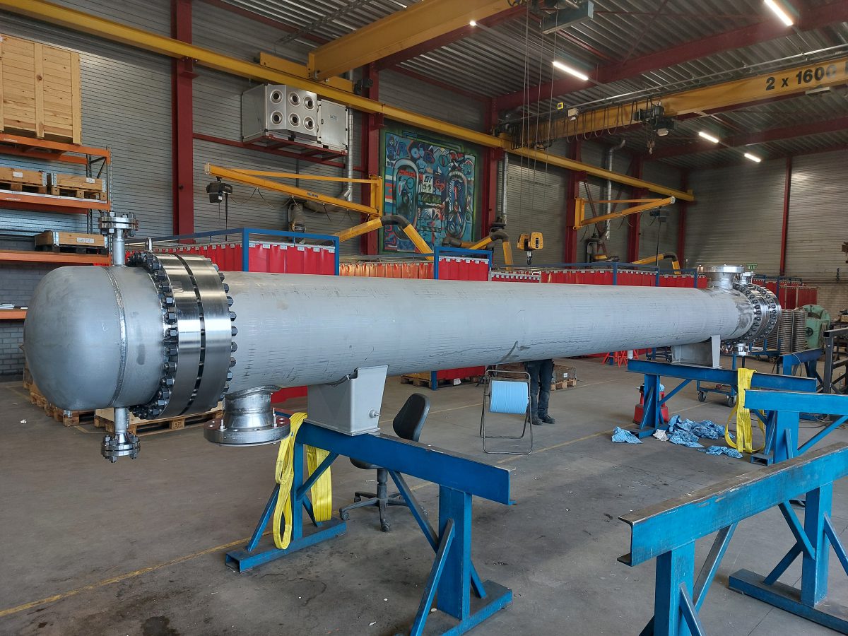
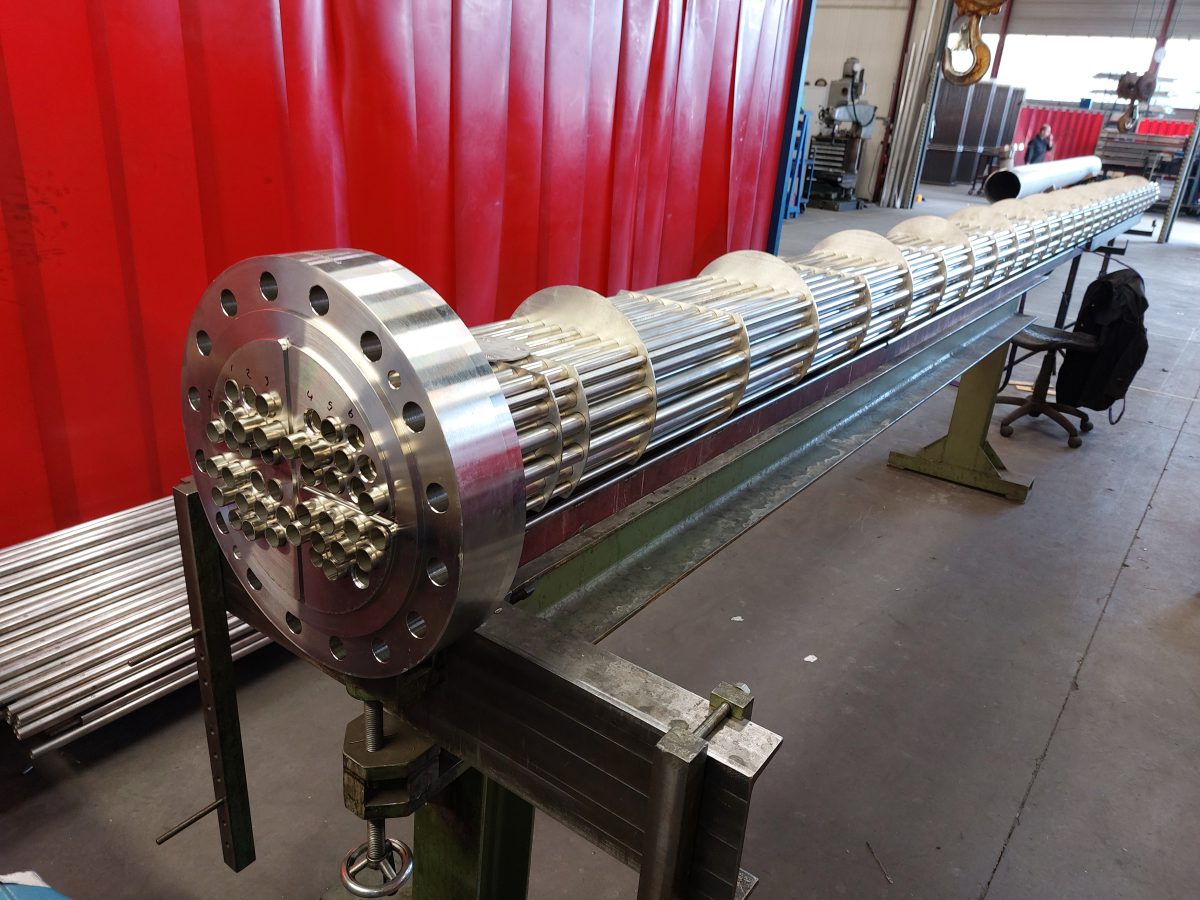
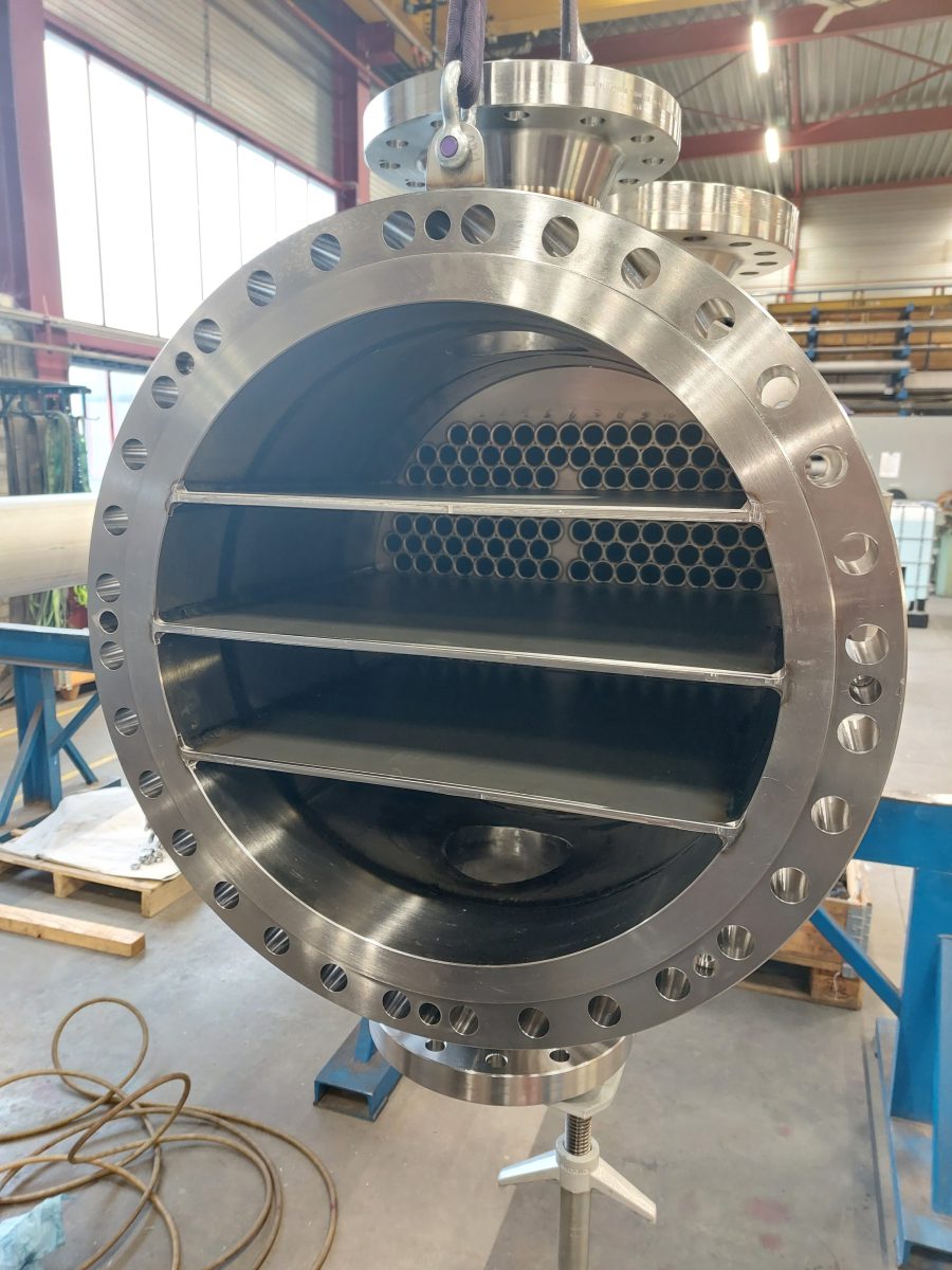
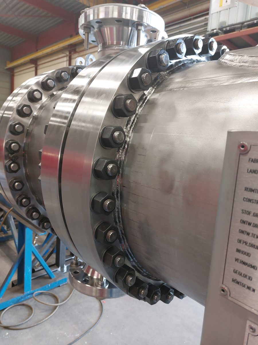
The installation in which these heat exchangers are integrated is used to dry CO2 with a silica gel adsorbent. Once dried, this CO2 is transported via pipelines to the North Sea to be stored in depleted gas fields.
To this end, in this part of the installation, the CO2 coming from a compressor is cooled back to ambient temperature using brackish water.
The other 3 heat exchangers in the installation are used for the regeneration of the adsorbent bed. A partial stream of CO2 is heated with steam before entering the saturated adsorbent bed in counterflow. To save energy, the hot exhaust gas from the bed is cooled back in a subsequent heat exchanger using cold regeneration gas. After this, the warm gas is cooled down further in the final heat exchanger, and the removed water is condensed and discharged. This final heat exchanger is also cooled with brackish water.
Because all heat exchangers are in series with each other, we were able to optimize the entire installation in consultation with the customer, both in terms of CAPEX and OPEX. In addition to this optimization, we were also able to save on costs by using super duplex clad material where possible instead of solid super duplex.
These are shell & tube heat exchangers, 2x type BEM, 1x type AEM, and 1x type BEU. Partly in super duplex, the rest in stainless steel 316(L). Designed and manufactured according to ASME VIII Div.1, TEMA, and API 660, supplemented by extensive customer specifications. At the user’s request, all heat exchangers were manufactured under Module G according to PED.